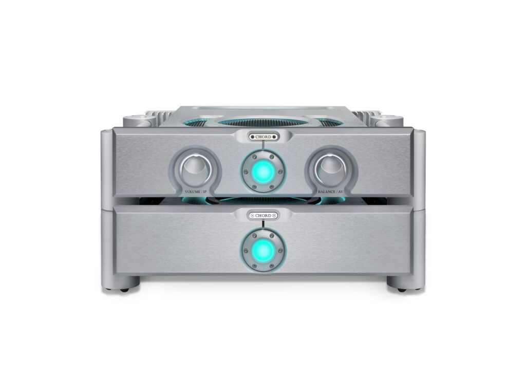
The whizz minds at Chord Electronics researched Class G output circuitry to get it work in their pioneering feed-foward ULTIMA schematics. And, naturally, the team found a few bright solutions along the way. This is a slightly abridged white paper from the company which tries to explain the innovations in layman’s terms. We also added explanatory slides at the end which were not part of the original white paper.
Chord Electronics Class G Amplification with Vertical MOSFETs
Chord Electronics has developed two new high-power Class G amplifier designs: one for the professional market and one for the consumer market. Both use high-power vertical MOSFETs as output devices, giving higher current capability than any other amplifier of comparable size.
Vertical MOSFETs have traditionally been regarded as unsuitable for linear audio amplification. Chord Electronics’ advanced proprietary drive and error-correction circuitry now allows them to be controlled precisely in their linear region, at high power and with very low distortion and noise.
The first production product to use the technology, the ULTIMA 7, is rated at a nominal 140 W RMS per channel into 8 Ω and has delivered a burst current of 33.9 A into a 1 Ω load. The topology is mature: no major issues remain to be resolved and further development will focus on specific applications as the technology is extended across new products and markets.
Class G amplification today
Class G amplifiers are already in use, but they are generally regarded as being of moderate quality and are found mainly in professional sound reinforcement, such as stage amplification for live bands. These designs have typically used epitaxial transistors or lateral MOSFETs.
All of these designs suffer from power glitches. As the signal waveform grows, the output transistors transition from conducting very little current to conducting high current and these transitions degrade the amplifier’s total harmonic distortion (THD).
Some high-power Class G sound-reinforcement amplifiers exist, but they use standard epitaxial transistors, which we consider likely to be relatively unreliable in this role. This prompted us to investigate whether ultra-high-power MOSFETs could be controlled in a Class G configuration to produce an ultra-high-quality amplifier with outstanding power for its size.
Lateral versus vertical MOSFETs
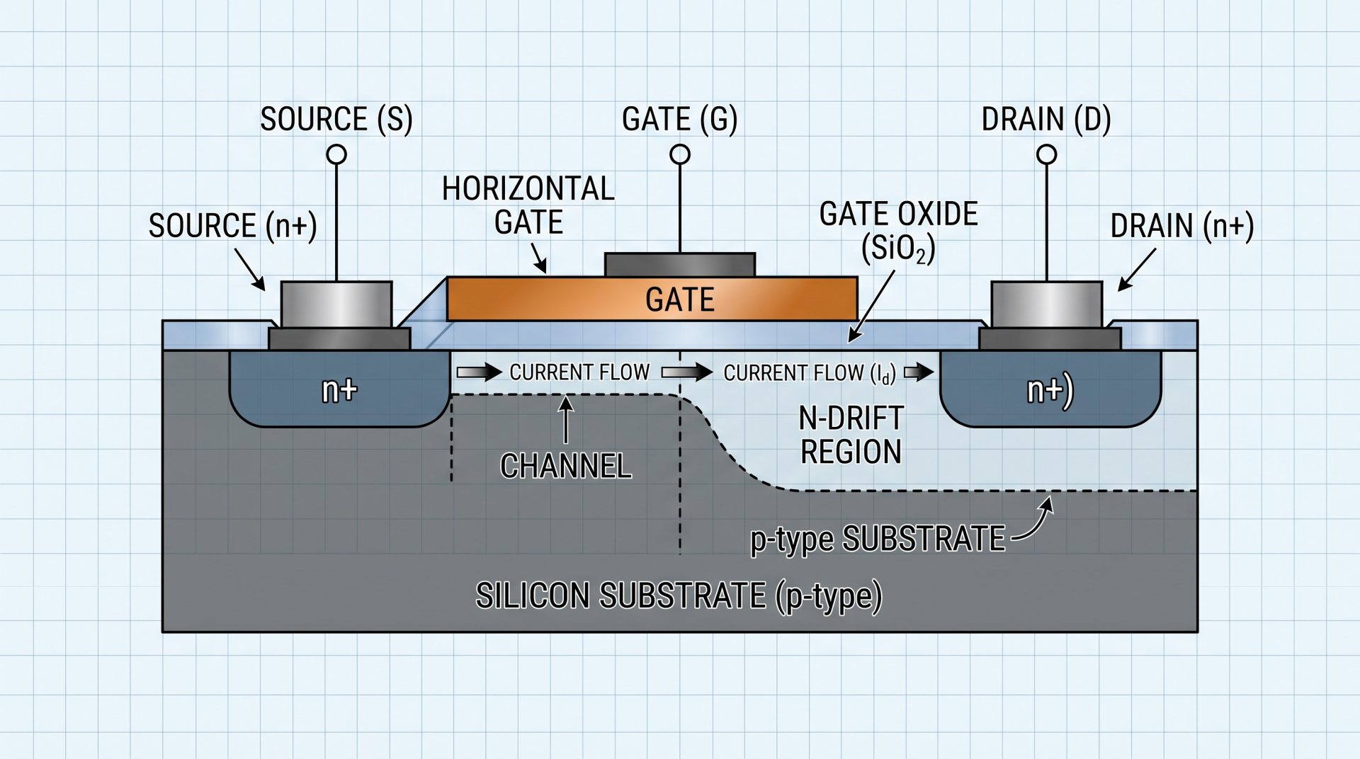
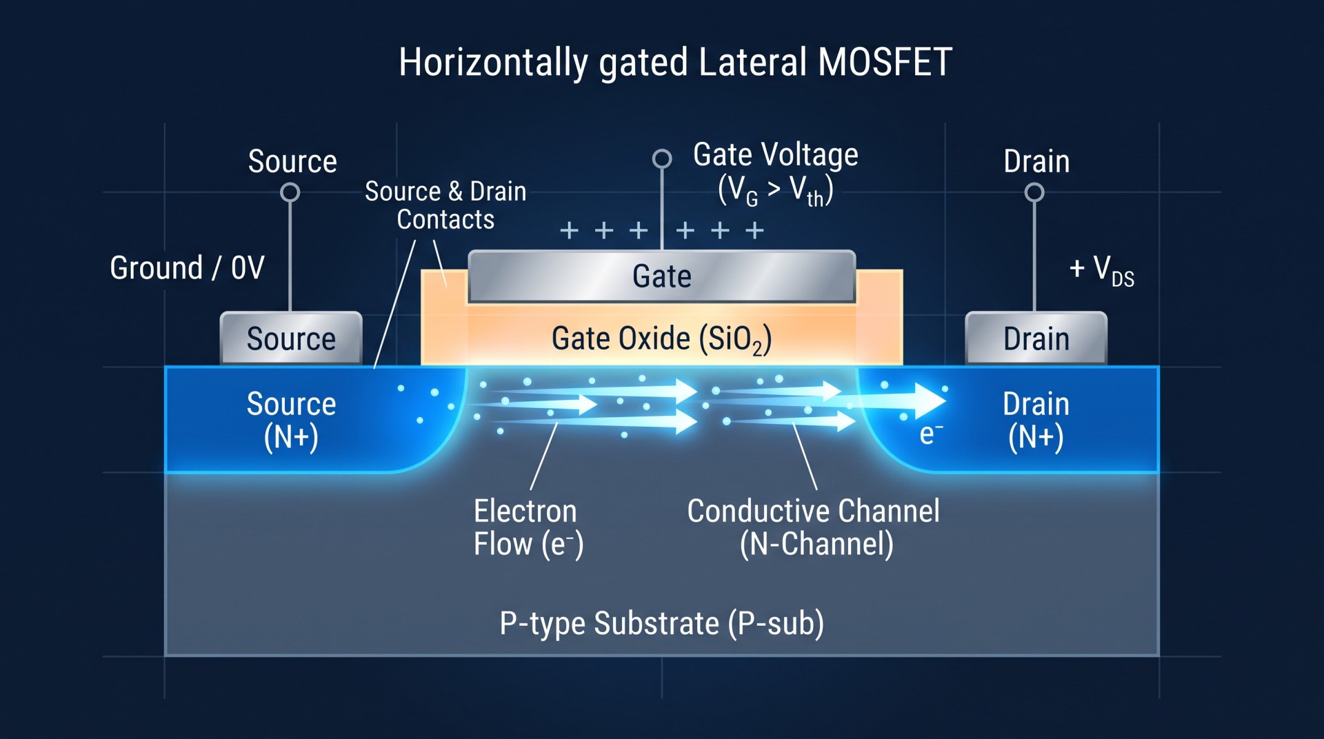
Lateral (horizontally gated) MOSFETs use an inefficient ‘waffle-iron’ gate structure, which requires a large and therefore expensive silicon die. Vertical MOSFETs have an efficient gate structure that allows an order-of-magnitude increase in current density for a given die size.
In practice, vertical MOSFETs are available with ten times the current capability of a comparable lateral device. This allows a modestly sized amplifier to achieve: far lower output impedance; greater current flow from the capacitor power reserve and tighter control of the loudspeaker: better ‘grip’, including better control of the loudspeaker’s crossover network.
The difference in scale is significant. A modestly sized amplifier using vertical MOSFETs can deliver burst currents of more than 150 A; with lateral MOSFETs, only 10–16 A would be practical.
Controlling vertical MOSFETs in the linear region
Vertical MOSFETs are far more difficult to control in linear operation than lateral devices, because they have a sharp ‘knee’ in their turn-on transition region. Until now they have mainly been used as power switches, for example in power supplies, where they are snapped either fully on or fully off. A conventionally designed Class G circuit simply cannot control the transition region finely enough to give good amplification performance.
Chord Electronics can now control vertical MOSFETs precisely in their linear region, neither fully off nor hard on, at high power, at frequencies beyond the audio band and with very low distortion and noise, making them suitable for world-class amplification.
The new design builds on our earlier work. We previously developed a dual feed-forward error-correction system based on the theories of Malcolm Hawksford of the University of Essex. This topology allowed us to control lateral MOSFET gates very precisely by applying dual feed-forward error correction between the gate controls and the output of each device.
During the Covid-19 period, we experimented with much smaller vertical MOSFETs for a desktop integrated amplifier, Anni. This confirmed that we could control small vertical MOSFETs with a few volts across them in a simplified amplifier design. The devices used in the new amplifiers are of a different order: kilowatt-class parts handling currents in excess of 170 A.
Design approach
We treat the design holistically. The amplifier must achieve very low distortion across the full frequency range and beyond, into difficult, realistic and highly reactive loads.
The drive circuits for the outer pairs of series MOSFETs are unique: they make the power transition between the high-power devices glitch-free, keeping THD and intermodulation distortion (IMD) well below 0.01 %, even when the amplifier is driven hard into a 2 Ω load at over 10 kHz. A few simple techniques ensure excellent thermal stability: once the bias has been set, it stays accurate.